ThreeDimensionalConfigurations/ChallengesPt3
Challenges Constructing Ellipsoidal-Like Configurations (Pt. 3)
This chapter extends the accompanying chapters titled, Construction Challenges (Pt. 1) and (Pt. 2). The focus here is on firming up our understanding of the relationships between various "tilted" Cartesian coordinate frames.
Various Coordinate Frames
Riemann-Derived Expressions
|
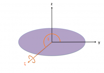
The purple (ellipsoidal) configuration is spinning with frequency, about the -axis of the "inertial frame," as illustrated; that is,
|
|
|
|
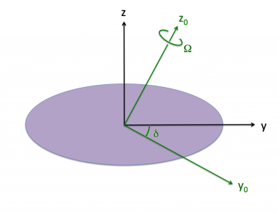
Also as illustrated, the "body frame," which is attached to and aligned with the principal axes of the purple ellipsoid, is tilted at an angle, , with respect to the inertial frame. Hence, as viewed from the body frame, we have,
|
|
|
|
Now, adhering to the notation used by [EFE] — see, for example, the first paragraph of §51 (p. 156) — we should write,
|
|
|
and, |
This means that,
|
|
|
and, |
As we have summarized in an accompanying discussion of Riemann Type 1 ellipsoids, [EFE] provides an expression for the velocity vector of each fluid element, given its instantaneous body-coordinate position (x, y, z) = (x1, x2, x3) — see his Eq. (154), Chapter 7, §51 (p. 156). As viewed from the rotating frame of reference, the three component expressions are,
|
|
|
|
|
|
|
|
|
|
|
|
|
|
|
|
|
|
where,
|
|
|
|
and, |
|
|
|
|
Rotating-Frame Vorticity
|
||||||||||
For our chosen Example Type I Ellipsoid, we have, and , in which case, and . |
 |
|||||||||
Tipped Orbit Planes
Summary
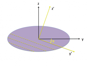
In a separate discussion, we have shown that, as viewed from a frame that "tumbles" with the (purple) body of a Type 1 Riemann ellipsoid, each Lagrangian fluid element moves along an elliptical path in a plane that is tipped by an angle about the x-axis of the body. As viewed from the (primed) coordinates associated with this tipped plane, by definition, z' = constant and dz'/dt = 0, and the planar orbit is defined by the expression for an,
| Off-Center Ellipse | ||
|
|
|
|
|
Notice that the offset, , is a function of the tipped plane's vertical coordinate, . As a function of time, the x'-y' coordinates and associated velocity components of each Lagrangian fluid element are given by the expressions,
|
|
|
|
and, |
|
|
|
|
|
|
|
and, |
|
|
|
As has been summarized in an accompanying discussion, we have determined that (numerical value given for our chosen example Type I ellipsoid),
|
|
|
|
where, and are as defined above. Also,
|
|
|
|
|
|
|
|
|
|
|
|
Note that this last expression has been obtained by making the substitutions, and , in the accompanying derivation's expression for .
Demonstration
In order to transform a vector from the "tipped orbit" frame (primed coordinates) to the "body" frame (unprimed), we use the following mappings of the three unit vectors:
|
Given that, by design in our "tipped orbit" frame, there is no vertical motion — that is, — mapping the (primed coordinate) velocity to the body (unprimed) coordinate is particularly straightforward. Specifically,
|
|
|
|
|
|
|
|
|
|
|
|
Recognizing, as before, that the relevant coordinate mapping is,
|
we have,
|
|
|
|
where,
|
|
|
|
Written in terms of the "body" frame coordinates, therefore, the 2nd and 3rd components of this velocity vector are, respectively:
|
|
|
|
|
|
|
|
|
|
|
|
|
|
|
|
|
|
|
|
|
|
|
|
|
|
|
|
|
|
|
|
These expressions perfectly match the body-coordinate expressions derived by Riemann (see above) for, respectively, and . The 1st component is,
|
|
|
|
|
|
|
|
|
|
|
|
|
|
|
|
|
|
|
|
So, implementing the mapping of , the first term inside the curly braces becomes,
|
|
|
|
|
|
|
|
|
|
|
|
|
|
|
|
Therefore,
|
|
|
|
|
|
|
|
|
|
|
|
|
|
|
|
|
|
|
|
See Also
- Description of Riemann Type I Ellipsoids
- Riemann Type 1 Ellipsoids (old introduction)
- Construction Challenges (Pt. 1)
- Construction Challenges (Pt. 2)
- Construction Challenges (Pt. 3)
- Construction Challenges (Pt. 4)
- Construction Challenges (Pt. 5)
- Construction Challenges (Pt. 6)
- Related discussions of models viewed from a rotating reference frame:
- PGE
- NOTE to Eric Hirschmann & David Neilsen... I have moved the earlier contents of this page to a new Wiki location called Compressible Riemann Ellipsoids.

|
|---|
|
Appendices: | VisTrailsEquations | VisTrailsVariables | References | Ramblings | VisTrailsImages | myphys.lsu | ADS | |

